Raspberry Pi lirc_rpi - (IR Remote control) LIRC GPIO driver

This guide has become obsolete by now! Please check these great guides instead:
https://www.instructables.com/Setup-IR-Remote-Control-Using-LIRC-for-the-Raspber/
https://blog.gordonturner.com/2020/05/31/raspberry-pi-ir-receiver/
Other guides are welcome!
The driver:
The driver is actually a modification of the lirc_serial module. I decided to create a new one separately because I couldn't hack it into the serial nor the gpio driver. The serial driver uses the DCD of the serial port, which is not implemented by the RPi. The gpio driver is created mainly to "talk" with TV tuner cards chip (here the module receives codes instead of pulse signals).
Installing the driver:
The driver is not in the main lirc repository, so the lirc sources must be patched first then the driver must be compiled. To do this you need to get the lirc sources. To compile a kernel module you need your kernel's header files.
(I didn't have the time to create a detailed HOWTO for every RPi binary distribution, so if someone could send me one I can publicate it here, so everything can be found in one place).
Howto install it on:
Recompile the kernel:
Follow the guide here.
After cloning the kernel, apply the patch in its root directory:
wget http://aron.ws/projects/lirc_rpi/kernel.lirc_rpi-0.3.patch
patch -p1 < kernel.lirc_rpi-0.3.patch

#Add the following to .config or enable in menuconfig:
CONFIG_RC_CORE=m
CONFIG_LIRC=m
CONFIG_RC_MAP=m
CONFIG_IR_NEC_DECODER=m
CONFIG_IR_RC5_DECODER=m
CONFIG_IR_RC6_DECODER=m
CONFIG_IR_JVC_DECODER=m
CONFIG_IR_SONY_DECODER=m
CONFIG_IR_RC5_SZ_DECODER=m
CONFIG_IR_MCE_KBD_DECODER=m
CONFIG_IR_LIRC_CODEC=m
CONFIG_STAGING=y
CONFIG_STAGING_MEDIA=y
CONFIG_LIRC_STAGING=y
CONFIG_LIRC_RPI=m
Loading the driver:
The driver has 5 parameters: debug, gpio_out_pin, gpio_in_pin, sense, softcarrier.
The default gpio input pin (PIN12 - GPIO18) is used when no input pin is specified as a parameter. The default gpio output pin for transmission is PIN11 - GPIO17. Please consult the RPi wiki page for more information about GPIO pins (here).
Example:
modprobe lirc_rpi gpio_in_pin=0 gpio_out_pin=1
The driver will use GPIO0, pin 3 on the RPi board as input.
Troubleshooting:
Check if the module could allocate the gpio pins.
mount -t debugfs debugfs /sys/kernel/debug
cat /sys/kernel/debug/gpio

The output should be something like this (you should see two gpio pins allocated to the lirc_rpi driver):
GPIOs 0-53, bcm2708_gpio:
 gpio-16  (led0                ) out hi
 gpio-17  (lirc_rpi ir/out     ) in  lo
 gpio-18  (lirc_rpi ir/in      ) in  hi
Check dmesg after loading the module with the debug parameter.
modprobe lirc_rpi debug=1

lirc_dev: IR Remote Control driver registered, major 252
lirc_rpi: module is from the staging directory, the quality is unknown, you have been warned.
lirc_rpi lirc_rpi.0: lirc_dev: driver lirc_rpi registered at minor = 0
lirc_rpi: driver registered!
lirc_rpi: is_right_chip bcm2708_gpio 0
lirc_rpi: to_irq 103
lirc_rpi: auto-detected active low receiver on GPIO pin 18
Run irw then check if the module succesfuly requested an irq.
cat /proc/interrupts
           CPU0
  3:      88963   ARMCTRL  BCM2708 Timer Tick
 52:       3251   ARMCTRL  BCM2708 GPIO catchall handler
 65:          2   ARMCTRL  ARM Mailbox IRQ
 66:          1   ARMCTRL  VCHIQ doorbell
 75:   51434882   ARMCTRL  dwc_otg, dwc_otg_pcd, dwc_otg_hcd:usb1
 77:        223   ARMCTRL  bcm2708_sdhci (dma)
 83:         24   ARMCTRL  uart-pl011
 84:       7123   ARMCTRL  mmc0
103:       3251      GPIO  lirc_rpi
The hardware:
The RPi's processor uses 3.3V levels and the pins are not 5V tolerant!!!
The receiver:
Te be able to capture the IR signals I used an infrared receiver that can operate at this voltage (like TSOP 1238). The classic TSOP 17xx and 18xx are unstable at 3.3V and won't work without some kind of level converter (IC, photo diode etc.).
As the LIRC manual states: "Most of these receivers come in variations adapted to a specific carrier frequency. You should choose the 38kHz types because most remote control standards use this frequency. 36kHz types should work as well. The receiver won't stop working if your remote uses another frequency but the range will decrease."
I would recommend these receiver modules (no test have been performed with these, but they should work...):
- TSOP2238, TSOP2438, *TSOP4838, *TSOP4438 (active high/low check the datasheet) (datasheet)
- *TSOP31238 (active low) (datasheet)
- *TSOP4038 (active low) (datasheet)
- *TSOP38238 (active low) (datasheet)
- *IRM3638N3 (datasheet)
- **TSOP1238 (active low) (datasheet)
- and many others ... (send them to me if you have found and tested new ones)
* Reported as working (Thanks go to: ice, Everett, George, druss, Djuri, Peter, Hannes)
** Was manufactured (according to old datasheets) as an 5V part. Consider ordering any other (Reported by: Tom)
The "hardware" is as simple as it seems. Power the IR receiver from the GPIO and use one of the GPIO ports to pass the signal to the RPi. By default the driver uses PIN12 (GPIO18) this can be configured with the gpio_pin parameter.
( ex.: modprobe lirc_rpi gpio_pin=0 this will configure the driver to use PIN3, check GPIO pinouts here)
TSOP1238 wiring(not all ir receivers have this pin order, please check the datasheets):
+-----------------------+ 3
|               data -> +---------------------o GPIO-PIN12 (GPIO18)
|                       |
|      ______________   |
|     /                 |
|    (                  | 2
|     \______________ + +---------------------o GPIO-PIN1 (+3.3V)
|                       |
|                       | 1
|                     - +---------------------o GPIO-PIN6 (GND)
+-----------------------+
* Current limiting resistor can be added to protect the RPi. Also optionally, a resistor and a capacitor can be added (check the receivers application circuit on the datasheet), but I think (somebody correct me if I'm wrong) it's safe this way.
RPi wiki site states: Maximum permitted current draw from the 3v3 pin is 50mA.
Actually these receivers draw ~5-10mA so it should be safe to use them this way.
The blaster:
                  GPIO-PIN2 (+5V)
                      o
                      |
                     | | 51 Ohm
                     |_|
                      |
                     _|_
                     \ /  --> TSAL5300*
                     ---  --> IR LED
                      |
           *BC337     |
         ___      |---'
  o-----|___|-----|
         10K      |->--
GPIO-PIN11            |
 (GPIO17)             |
                    ----- GPIO-PIN6 (GND)
                     ---
                      -
*Any kind of IR LED should work (pick one that operates at 940nm peak wavelength), check out the datasheet for power requirements. Also any kind of NPN transistor should work that can forward ~300mA current.
This is only a test circuit, so if you want something more sophisticated (with a better range) take a look at Brian's schematic here (the way this works is brilliant).
A more sophisticated transceiver (thanks to Tamas Tevesz):
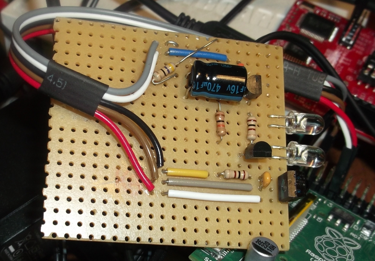
Schematic:
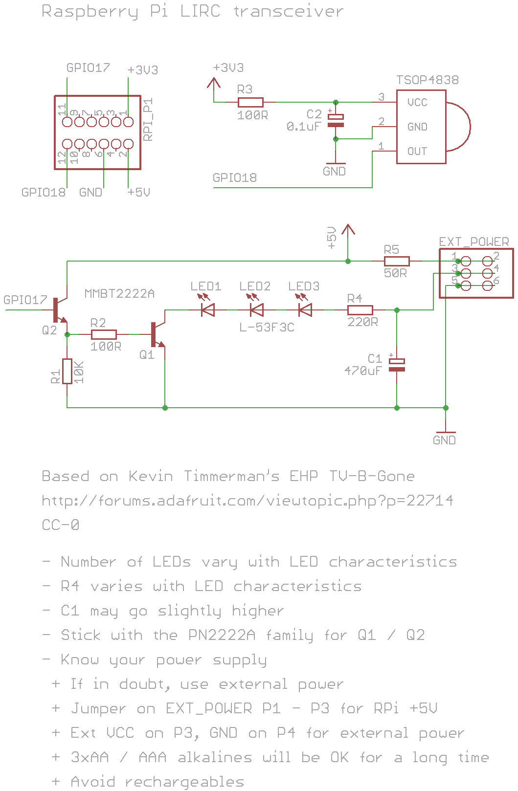
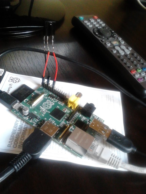
Image of my receiver
Questions:
Please send me a mail if you have questions: aron [at] aron.ws
Modified: 2016-09-06